 Buses / Connectors
16 bit connections
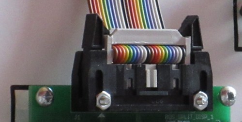
The Megaprocessor is a 16 bit processor so we have 16 bit data buses connecting registers, multiplexors, adders etc. There's quite a lot of 16 bit connections. Having 16 individual wires for each would have been very messy and confusing. Having to solder each of these each would have been horrendously tedious and error prone so the obvious answer was to go for ribbon cables and IDC (Insulation displacement connections) connectors. Add a few grounds and I decided to go for 20way cables and connectors.
This was sensible enough. It was certainly not a bad decision. It's just that it wasn't a brilliant solution either. I still don't know what the right answer is.
The only actual error is that I didn' t properly anticipate what the address bus would look like. The address itself is 16 bits wide, just like the data. The trouble is that there is also an associated direction (read/write) signal and an enable signal. To the extent that I thought about them at the start my vague thought was that they would be handled as essentially independent point to point wires. That wasn't a bad guess but when it came to actually building the system I (too late) eventually realised that I didn't want individual signal wires going between modules and frames, just wide connectorised buses). I therefore had to define a second bus "standard" with 16 bit data and a couple of control signals and get a second family of interconnection boards made for handling address buses. It wasn't a disaster, I didn't have to redo anything. But it was more money and time that a few minutes thought at the start might have saved.
The next issue relates to clarity. The ribbon cables are relatively wide (one inch, 2.5 cm) and so take up quite a bit of real estate on the front of a module. In quite a few situations they obscure the schematic showing control signals which is a bit of a shame. I did spend a bit of time contemplating how I might take them through the board and route them round the back of the module. The trouble is that the hole would have to be big enough to take the connector and I couldn't think of a way of drilling/cutting such a hole in a neat fashion. Or at least not without it taking an infeasible length of time. Whilst I like the way the ribbons show data moving round, the clutter they introduce is one of the things I'm particularly disappointed by.
And then there is the expense. I've spent far more money on these than the other components (transistors, LEDs & resistors). I do wonder whether if I'd done things differently I could have taken advantage of some cheap standard cables. They would also have saved me the work of making up the cables (I've had to make up nearly 400).
My current thoughts as to what I should have done is standardised on an 8 bit interconnection using RJ45 connectors and ethernet cables. Ethernet cables have 4 twisted pairs which would give us 8 wires. The data bus would use two connections and the address bus would be done as three with one of the connections only carrying 2 signals.
- It would have been cheaper.
- Two ethernet cables have a smaller width than the 20way ribbon so would have obscured less of the board. Or alternatively as you don't need a huge hole to take an RG45 perhaps I could have taken the cable through the board and run it round the back like the single control signals. (Actually you probably would want to take the cables round the back as the cables would come in fixed standard lengths so there'll always be some slack you'd want tidied out of sight.)
- As an extra bonus there are a few places where I have to split out/join together the LSB and MSB of a 16 bit bus, and with 8 bit buses you'd get that for free.
- The only downside I can think of at the moment is that I think the footprint of two RJ45s is greater than that of the connector I did use, but there's not much in it.
- Too late now.
1 bit connections

I'm not sure I went down the right route here either. Soldering directly to the board seemed like a bad idea. I wanted something I could connect/disconnect to easily for testing and then fit into main system. So I went for these clippy things. I used the brass pins for input signals and the coloured ones for output signals and power. It worked out ok. But they are surprisingly expensive, and my soldering connections were sometimes a little messy.
I should probably have investigated some other options in more depth. In particular some crimp connections. But at the start when I was wondering what to put on my first board I didn't know what lay ahead and the thought of making up crimp terminals did not appeal. I'd only ever made them with pliers and it's not been a lot of fun. If I'd known just how big the project was going to get then I'd have invested in the right crimping tools and maybe made a different choice. Once I'd had the first few boards made it seemed to late to go back and start over with a different choice.
- Home
- Vital Statistics
- Progress
- Architecture
- Stepping Stones
- Programming
- Peripherals
- Construction
- Cost & Materials
- Good, Bad & Ugly
- History
- Build Faults
- Flip Flops
- Modelling
- Architecture Choice
- Logic Type
- 7 segment
- Board Shape
- Dual Output
- ALU
- SRAM
- Speed
- Speed 2
- Buses
- Area
- Efficiency
- LED supply
- Multiplexor Problem
- Multiplexor Errors
- Surface Mount
- Solder
- Health & Safety
- Web
- Links
- Contact

© 2014-2016 James Newman.