 Build faults
In my youth I spent quite a lot of time modelling and making things in general. And (as I remember things) I was reasonably skilled at crafty stuff. However it seems the years have taken their toll and my labs skills aren't great. On this page I collect together my various mishaps on the building side of things.
Backwards Transistor
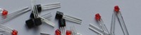
To make building up the circuit boards as easy as possible I used the silkscreen to tell me:- what values to use for resistors
- which way in to put the transistors
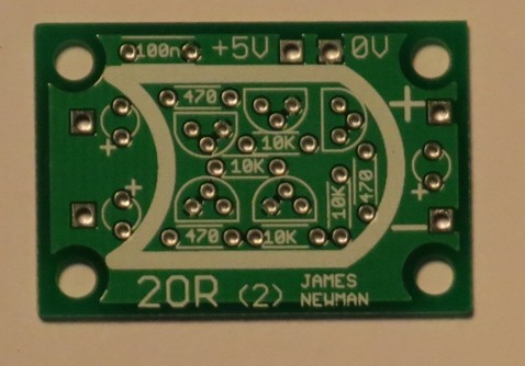
So fairly fool proof you'd have thought. But I still managed to get maybe a dozen or so transistors in backwards across the project. And I find them really difficult to spot. See how you get on. There is one (only one) in backwards in the image below.
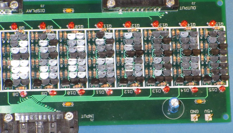
Depending on the consequences I could sometimes work out what had happened almost immediately. Sometimes it took hours; only when I was able to deduce exactly which transistor was going wrong could I see that I'd put it in backwards despite having been looking at it for all that time.
IDC connectors
There's a lot of ribbon cable in the Megaprocessor, of the order of half a kilometer I think. And a lot of connections, maybe 500 or so. I made up the vast majority successfully but I messed up a dozen or so.
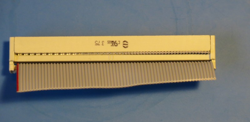
Squint cable
This was the first one I got wrong and it caused me hours of bewilderment. The connections on the right were fine, a few on the left were definitely not made but there were several in the middle that made sporadic contact. As I was testing a new module at the time which had its own faults I ended up chasing my tail for a while.
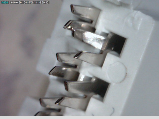
Bent teeth
The IDC (Insulation Displacement Connector) connectors work with little teeth that slice into the ribbon to make contact with the conductors. Somehow every now and then I would manage to bend a few teeth out of line . Here are some pictures of the first time I did that.
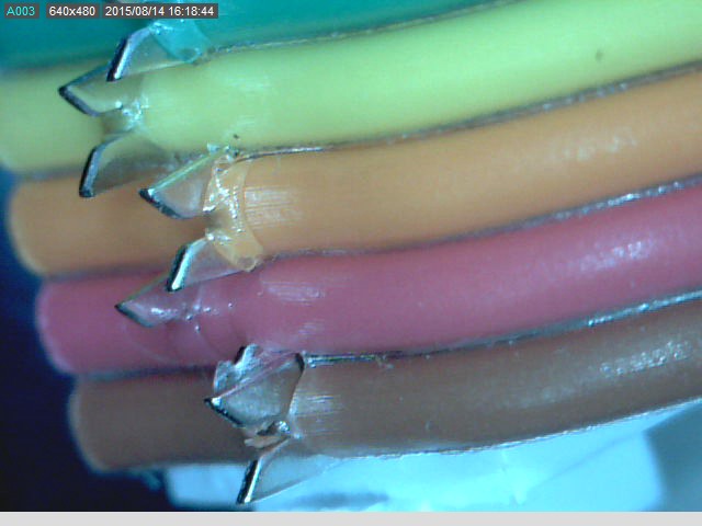
One of the teeth that should be pinching the red cable has been
shifted to cut into the brown, giving a short circuit between
them..
This kind of error leads to both shorts between adjacent cables
and sometimes to no connections. It can be very confusing
especially as normally the first time the cable gets used is for
some fresh hardware which will have its own problems.
Transposition
And of course every now and then I'd make the obvious mistake and transpose the cable. I think most times I realised just as soon as I'd finished clipping on the strain relief. Which is annoying. But not as annoying as only working out what has happened after you'd threaded a couple of meters of cable into the system and then spent an hour or two trying to work out what had gone wrong. The cable at the bottom is good, the cable at the top is wrong.
Not sure its obvious to me even when I know the answer.
Not pushed home
These only seemed to crop up during integration. Maybe there were nearly pushed home when I was testing the modules and then later worked loose as I shuffled frames around.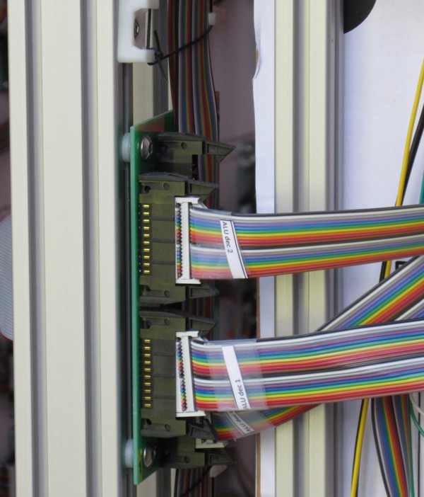
Shorts
Short to frame
This was an obscure fault where a couple of inconsequential misdemeanors combined to create a fault. The board below behaved as if the left hand input of the left board was always at 0V.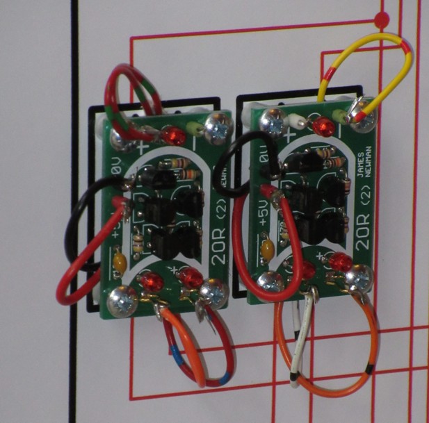
First I tried to debug the board, couldn't find anything wrong. Then I tried to debug the board that sourced the orange wire, couldn't find anything wrong. It turned out that:
- the left hand mounting screw is shorting to the terminal - its not supposed to but this shouldn't matter as its screwed into plywood
- the screw is too long and penetrates, just, all the way through the plywood - which shouldn't matter
- but on this occasion we happen to be over one of the supporting aluminium bars of the frame so we essentially get a short to ground.
Solder Flashes
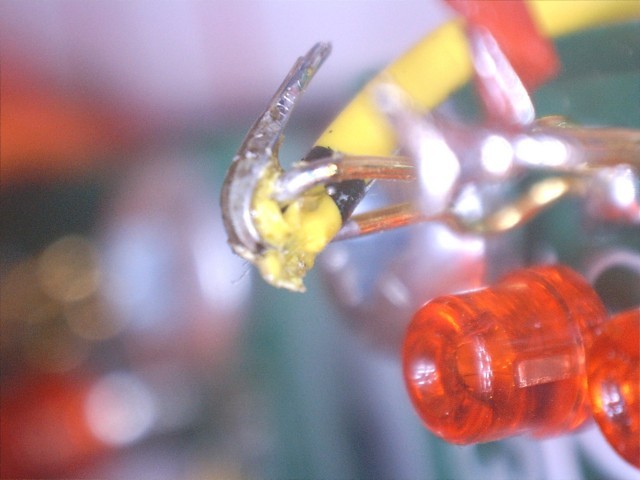
I have no proof but I now believe that some of my problems were caused by "solder flashes". Sometimes boards misbehaved in quite obscure ways and I would resort to replacing transitors in what I hoped was the right place and the board would start working again. Some of these (especially in the early days) could have been the result of transistor death (see below) but others didn't seem to be failing the right way for that. After rather more than desirable of these failures I investigated a bit more. So the next time I thought about removing a transistor I tried to look at what might have happened. After chopping off the transistor this is what I saw: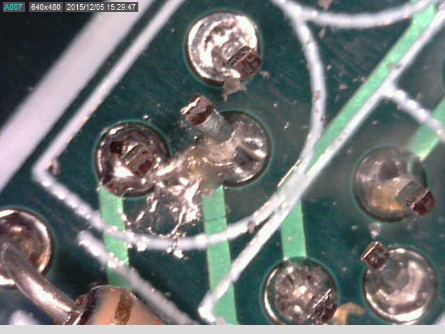
It looked to me that there was possibly a solder bridge between two of the legs. How did that get there ? My guess is as follows:
When building up a board I solder a few components at a time. As I work my way across the board I occasionally blob some solder on a pad that doesn't yet have a component in it. So I have to remove the solder, which I do using a de-soldering pump. On occasion the de-soldering pump leaves a thin flash of solder on the board. I think I wasn't scrupulous enough when cleaning up, I tended to be concentrating on the solder side of the board, rather than the component side.
After I made this deduction I tried being more conscientious in my cleaning and I think things got better after that time.
Clipped Leads
On one occasion I manged to clip the leads after soldering so as to leave them shorting, only just, together.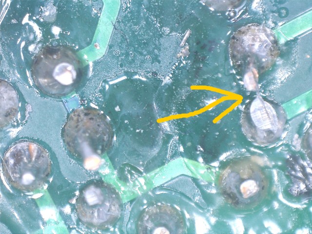
Soldering - forgetting to
This is my favourite error in the sense that if I have to make an error this is the one I'd chose. On quite a few occasions I've picked up a board that's failed a test, turned it over and found I've forgotten to solder half the connectors, or missed out a whole line of transistor legs. Its great...its immediately obvious what's wrong and really easy to fix. (But it is rather worrying that I can make such a gross error. How could I not have seen the missing solder when doing the final inspection?). This is one of my more egregious examples.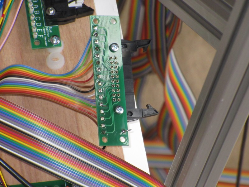
Soldering - dry joints
This is my nightmare fault. I've not yet tried to calculate how many solder joints I've made but it must be some hundreds of thousands by now. And all have to be good for the Megaprocessor to work. If I have many dry joints then reliability will be hopeless and the project will be dead in the water. So far I don't believe I have found any significant number of dry joints, or indeed any. Talking to some of my friends/colleagues skilled in the art it may be that it is the use of lead solder that is saving me.Update 29th April: During integration I have found a few bad solder joints. These have not been on the circuit boards as such but when soldering point to point wires onto their terminals. They look ok to my eyes. I can just about see something suspicious under magnifying glasses when I know where the problem is. It becomes clear under the microscope. It's the one on the left here, from this angle doesn't look too bad.
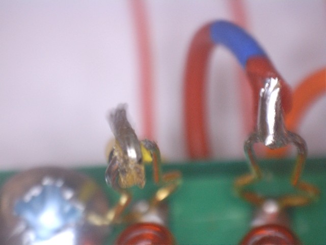
But from the side:
I've not cut off the insulation cleanly and a little bit has got in the way stopping the solder from properly wetting and flowing over the terminal.
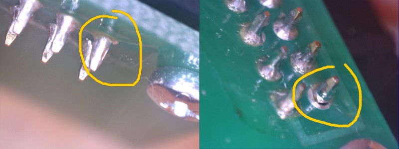
Update 20th May 2016: Found my first proper dry joint. It looked fine from the easy viewing angle but from the reverse side, and using magnification, it is apparent the joint is poor.
Transistor Death
This was the scary problem at the beginning of the build. I would "carefully" solder some boards up. Test each individually. Mount them on a board. Solder them together. test them as a whole and find that some boards had stopped working. And they would have a similar failure mode, I would tend to see some weakly on LEDs on my boards. What had happened ?The obvious candidate when dealing with MOSFETs like the 2N7000 was damage from electrostatic discharge. This didn't make a huge amount of sense to me as why were the transistors able to survive my soldering and testing but not survive mounting on the board, much the mildest stage of the operation ? Anyway I invested in a bunch of antistatic mats and wrist straps (should have done that at the start anyway). Didn't make things any better.
Some of my friends suggested it might be glitches on power up, I use a different PSU for testing from the one used to drive the frames. So I spent about a day just power cycling the mounted boards and found that none failed so it didn't seem that it was the power supply to blame.
After some time I eventually twigged as to who was to blame.
It was Henry !!
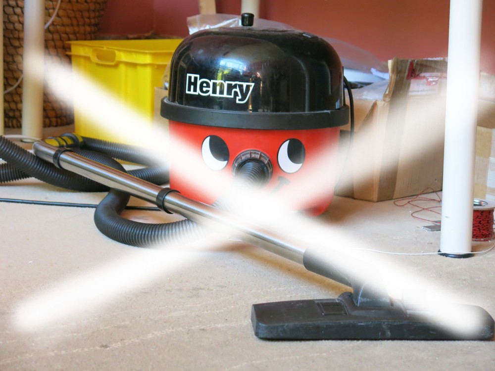
You might be wondering why I hoover electronics. If you look at a picture of one of the completed frames you might be able to see that some of the ribbon cables are tied in place to stop them flopping about. I have to drill the holes for the string after I've mounted the electronics. This covers everything in dust, so I was hoovering to clean up the sawdust.
Wiring Transposition
I usually make a couple of errors when wiring up a module. The control modules have one to three hundred point to point connections. The main source of error is that I have to do the wiring on the reverse of the module, but the wires get soldered on the front after being threaded through some holes. So there's plenty of scope for getting a left/right transposition error or getting confused as to which gate I'm wiring. So every now and then I got it wrong.To give myself some chance of success I tried to find as many different coloured wires as a I could, just shy of 20.
I also had a bit of a system to try and keep track of what went where. As I put in each wire I marked up a full size picture with the colour of the wire I was using for that particular connection. In addition I had a suitably reversed schematic glued to the reverse of the module which I also marked up as I went along. Most times when I made a mistake I'd find out only a short while later when I tried to make another connection and one of the schematics would indicate I was trying to do one end or the other twice.
- Home
- Vital Statistics
- Progress
- Architecture
- Stepping Stones
- Programming
- Peripherals
- Construction
- Cost & Materials
- Good, Bad & Ugly
- History
- Build Faults
- Flip Flops
- Modelling
- Architecture Choice
- Logic Type
- 7 segment
- Board Shape
- Dual Output
- ALU
- SRAM
- Speed
- Speed 2
- Buses
- Area
- Efficiency
- LED supply
- Multiplexor Problem
- Multiplexor Errors
- Surface Mount
- Solder
- Health & Safety
- Web
- Links
- Contact

© 2014-2016 James Newman.