 Speed
Speed
I messed up here.
It has to be said though that the Megaprocssor isn't about speed. To be able to see the lights flashing and follow what is going on I expect that most of the time it will be run at 1 Hz or less. That said it would be nice to have some performance available, there will be occasions when you want to just race through a bit of code to get to the next fun section.
To the extent that I thought about it my expectation was that a MHz would be not unrealistic but I'd happily settle for a few hundred kHz. A few months back it looked like the answer would be about 20kHz, I'm now hopeful of somewhere about 50 kHz.
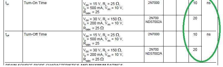
The reason for my early optimism was the values for the turn on/off for the 2N7000 which is the FET I'm using
The slowest part of the Megaprocessor is its 16 bit adder. These are ripple adders so you won't get a valid answer from them till the answer has worked its way all the way up from the least significant bit through every single bit up to the most significant. This is a path of about 30 gates length. There's some other things logic that needs to be done to set up the adder and store the answer once its produced. Call it 50 gates which at 20ns a time is 1μs so 1MHz. But there's some long wires to drive which will slow things down so the answer would be more like some 100 kHz,.
Trouble was that I hadn't looked properly at the data sheet, there's some more numbers.
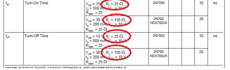
The times of 10/20 ns were achieved with a load resistor of only 25/150Ω and so the transistor was passing currents of hundreds of mA. I use thousands of transistors. Yes some are in series but even so that would scale to needing a power supply capable of delivering thousands of Amps which is just not sensible. Or feasible. I chose a load resistor of 10kΩ so that the transistor is only passing half a mA. I didn't appreciate just how much this would affect the turn/off times. Because of the "high" load resistor my gates take round about 1μs to respond to changes in their inputs. So we would now expect 50 gates to take about 50μs giving us the 20kHz.
I only realised what the problem was quite late on (my early tests were all about correct logical operation, I wasn't looking at speed) when it was much to late to change the resistor value as most of the boards had been built.
However the fact that the speed of operation is determined predominately by the speed of the adders means that we can get a disproportionate benefit from rebuilding the adders. Building an adder with 1kΩ rather than 10kΩ resistors made it about 8 times faster. In the trace below I have an adder built with 10kΩ resistors side by side with one using 1kΩ resistors set up to do 0 + 0xFF. I change the carry in signal and look to see when I get a change to the carry out.
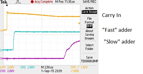
The trace above shows that the 8 bit adder now takes about 2.5μs (rather than about 19μs), so a 16 bit adder will take about 5μs. There will still be 10-20 slow logic gates to get through at about 1μs a time for a total about 15-25μs, hence my hope that now the processor will run at about 40kHz. If the non-adder critical path logic gates are identified we may find that a further significant speed up can be obtained without too much pain.
If I had my time again I'd definitely use a smaller load resistor in some strategic places. Probably 1kΩ for the adders and simple logic gates and maybe stick to the 10 kΩ for the big but "shallow" things such as multiplexors and registers. Dropping all down to 1kΩ, or lower, may make the power supply too difficult/expensive. I might also reconsider using a faster adder architecture.
- Home
- Vital Statistics
- Progress
- Architecture
- Stepping Stones
- Programming
- Peripherals
- Construction
- Cost & Materials
- Good, Bad & Ugly
- History
- Build Faults
- Flip Flops
- Modelling
- Architecture Choice
- Logic Type
- 7 segment
- Board Shape
- Dual Output
- ALU
- SRAM
- Speed
- Speed 2
- Buses
- Area
- Efficiency
- LED supply
- Multiplexor Problem
- Multiplexor Errors
- Surface Mount
- Solder
- Health & Safety
- Web
- Links
- Contact

© 2014-2016 James Newman.