 Peripherals
Building a processor is all very well but it's no use by itself. It needs something to talk to. As the peripherals are outside the procesor and not part of it I was happy (very happy) to leave behind my transistor obsession and use some easier technologies.
Control & I/O Frame
The Megaprocessor joins the outside world in this frame.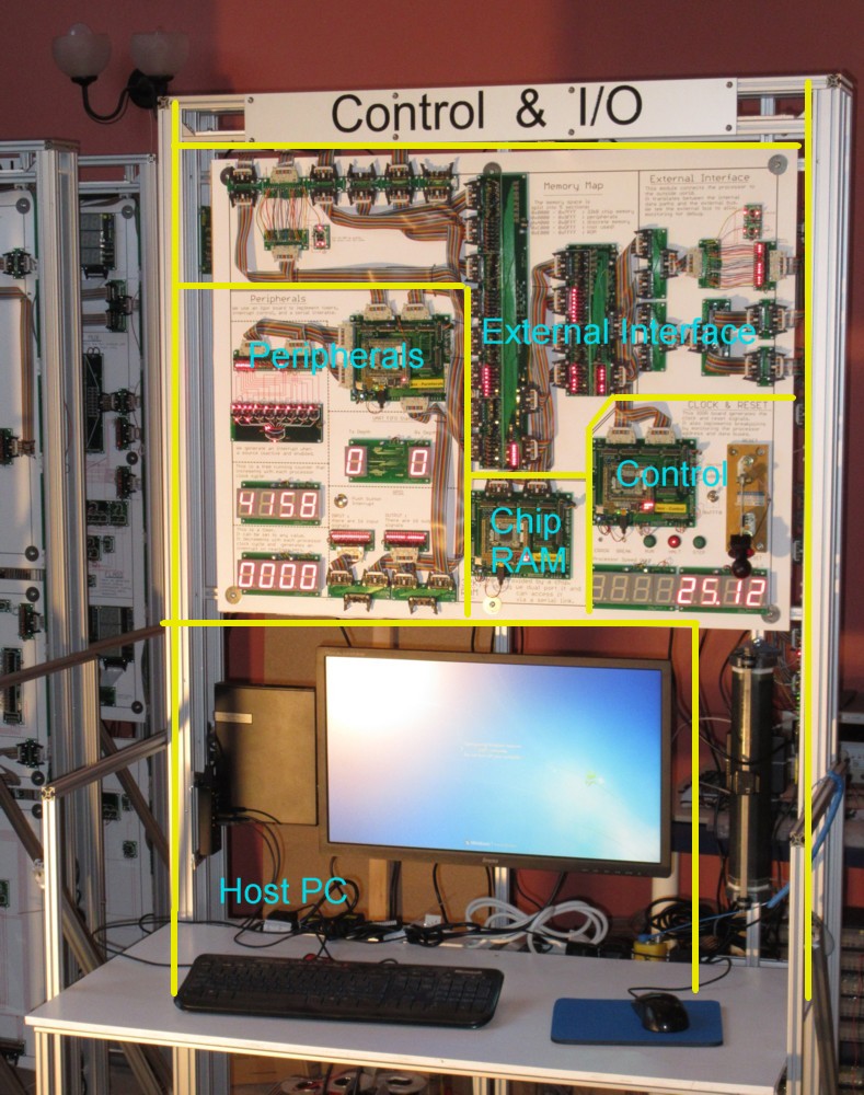
The external interface of the processor runs across the top of the frame. This is part of the processor and so is implemented using discrete components. Here we split the address space into five sections for:
| chip RAM | 0x0000: 0x7FFF |
| Peripherals | 0x8000:0x9FFF |
| discrete RAM | 0xA000:0xBFFF |
| (spare) | 0xC000:0xDFFF |
| ROM | 0xE000:0xFFFF |
A control section generates reset and clock.
There is also a PC. This can run the assembler for creating programs and can download them over a serial interface to the chip RAM. A second serial interface allows it and the Megaprocessor to talk to each other.
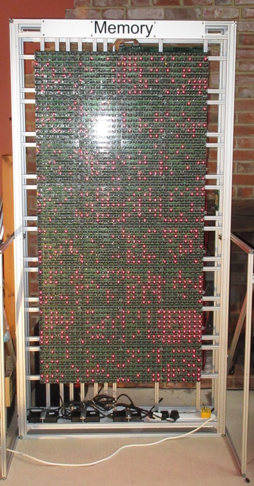
Discrete RAM
This is 256 Bytes of static RAM built with the same technology as the main processor itself, i.e. discrete transistors. Each bit of RAM has its own LED so that you can see the contents of the memory. This means it acts as a display as well as memory.It was an epic amount of work, it contains more than half the transistors of the whole project, it needed its own frame.
Here is a video of it in action whilst being tested.
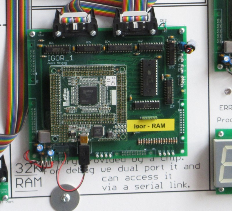
Chip RAM
To run some larger programs I added a 32kB RAM as a chip. This was done using an Igor board. I arranged it so that it was dual ported with a PIC which allowed me to download programs.I added a feature to the Megaprocessor so that you could change the location of its vector table between 0x0000 (where this chip RAM lived) and 0xFFF0 where the ROM lives. This meant that I could get away without initially building a ROM and get to see the Megaprocessor running sooner than otherwise would be the case.
Peripherals
An Igor board implements a few simple peripherals.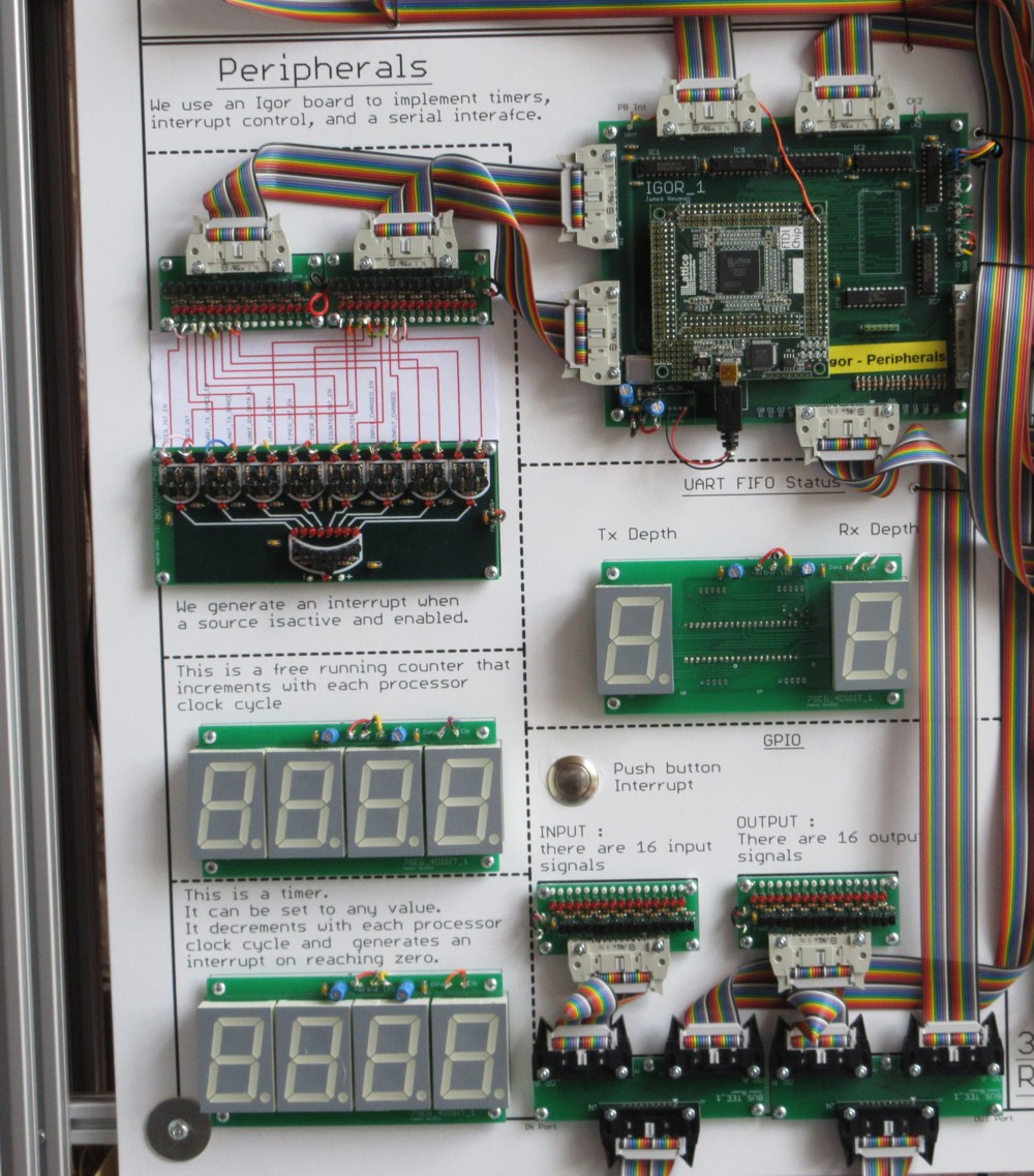
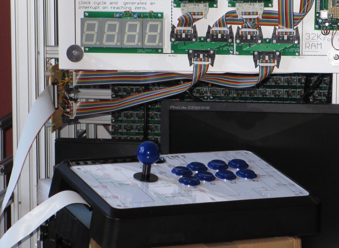
There is General Purpose I/O (16 bit in and 16 bit out). LEDs show the state of each. I modded a Venom Arcade Stick to connect to these I/O to give me some buttons and a joystick.
There is an interrupt controller. There are 6 interrupt sources, each can be individually enabled. The registers for doingthis are within the FPGA, but the calculation of the interrupt itself is done using good old transistors. The possible interrupts are:
- Push button
- UART Tx FIFO empty
- UART Rx FIFO not empty
- Counter reaches zero
- Timer reaches zero
- Input (as in the GPIO) changed
There is a Timer and a Counter, the current values of both are displayed on 7 segment displays.
- Counter:
- is free running and just increments. Its current value can be read by the processor. It generates an interrupt on rollover.
- Timer
- this decrements. It can be stopped and started. It can also be set to a value. Its current value can be read by the processor. It generates an interrupt on rollover.
There is also a UART. The current occupancies of the Tx and Rx FIFOs are displayed.
Display
There are two display options.- The discrete RAM (see above) can act as a giant 32*64 dot matrix display.
- Alternately my intention is that the host PC can act as a graphics slave. The Megaprocessor can send it display commands over the serial interface. I've not implemented this yet. (I was actually initially going to do this with a Raspberry Pi. That idea faded away when I was trying to work out how to do all the other peripherals. Now that those functions are offloaded onto Igor boards maybe the Pi can make a comeback.)
(I did originally want to implement an emulation of a vector display from teh old old days. That's going to have to be a project for another day).
ROM
This has not yet been implemented. I managed to circumvent the need for this by being able to download programs to the chip RAM and boot from there.Control
This is not really a peripheral. It generates the reset and clock for the processor so its more infrastructure support.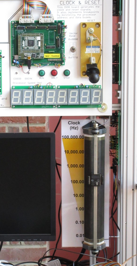
There's a big switch for the reset and a big slidey rheostat for setting the clock speed. The clock speed can be varied continuously from .01 to 100,000 Hz. The clock can also be stopped and stepped one cycle at a time.
It also monitors the processor bus and can halt the clock under specified conditions, i.e. breakpoints. Breakpoints are provide through a serial interface.
In addition the Igor board contains a VHDL implementation of the Megaprocessor. This shadows the processor operation and if (when?) the two diverge we have a hardware bug so the clock is halted to allow me to debug it.

© 2014-2016 James Newman.