 Frames
This is a gallery of the frames that make up the
Megaprocessor.
State & Status
This holds the controlling state machine (top module) and the Processor Status register (PS). The PS itself is in the middle module, the lowest module calculates the values for the PS on the basis of result codes and the current instruction.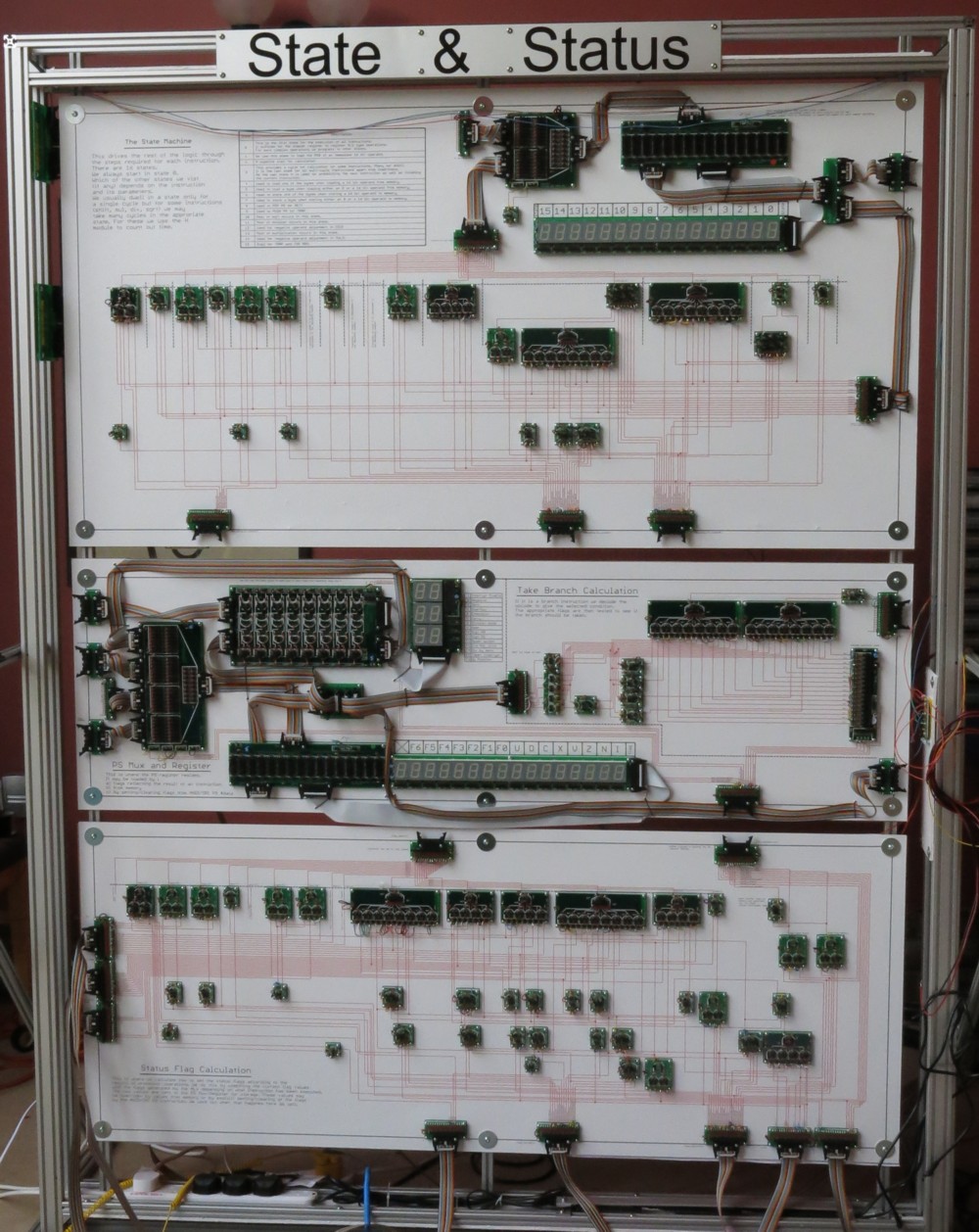
Input & Decoding
The top module holds the currently executing instruction. The lower three modules decode the instruction to generate control signals for the other frames.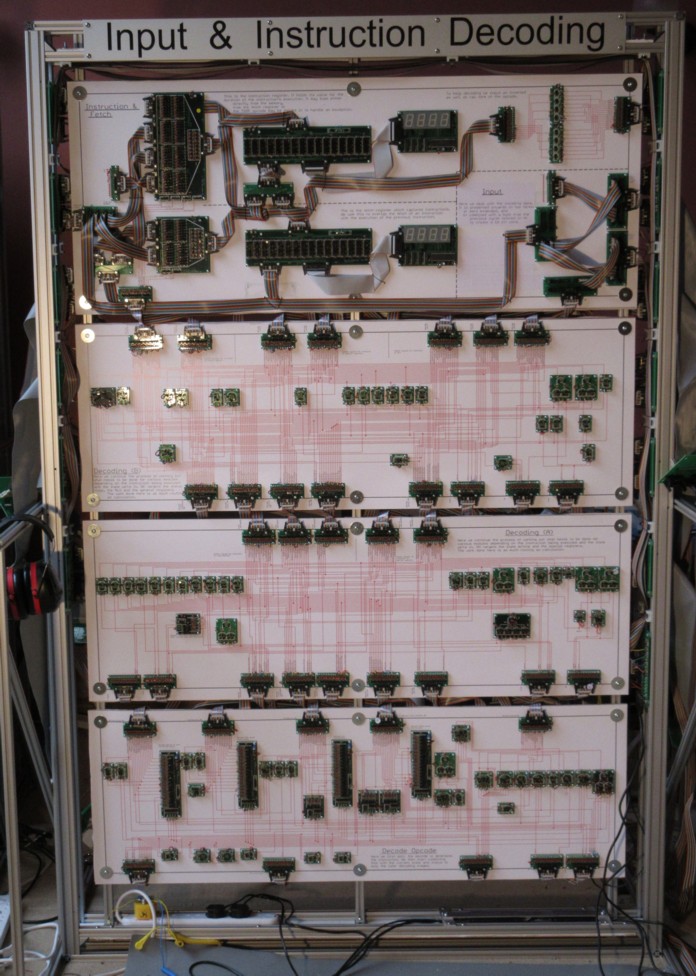
Special Purpose Registers
The top module holds the Stack Pointer (SP), external address, Program Counter (PC). write data and Helper (H) registers with their associated multiplexors. The lower module generates the control signals.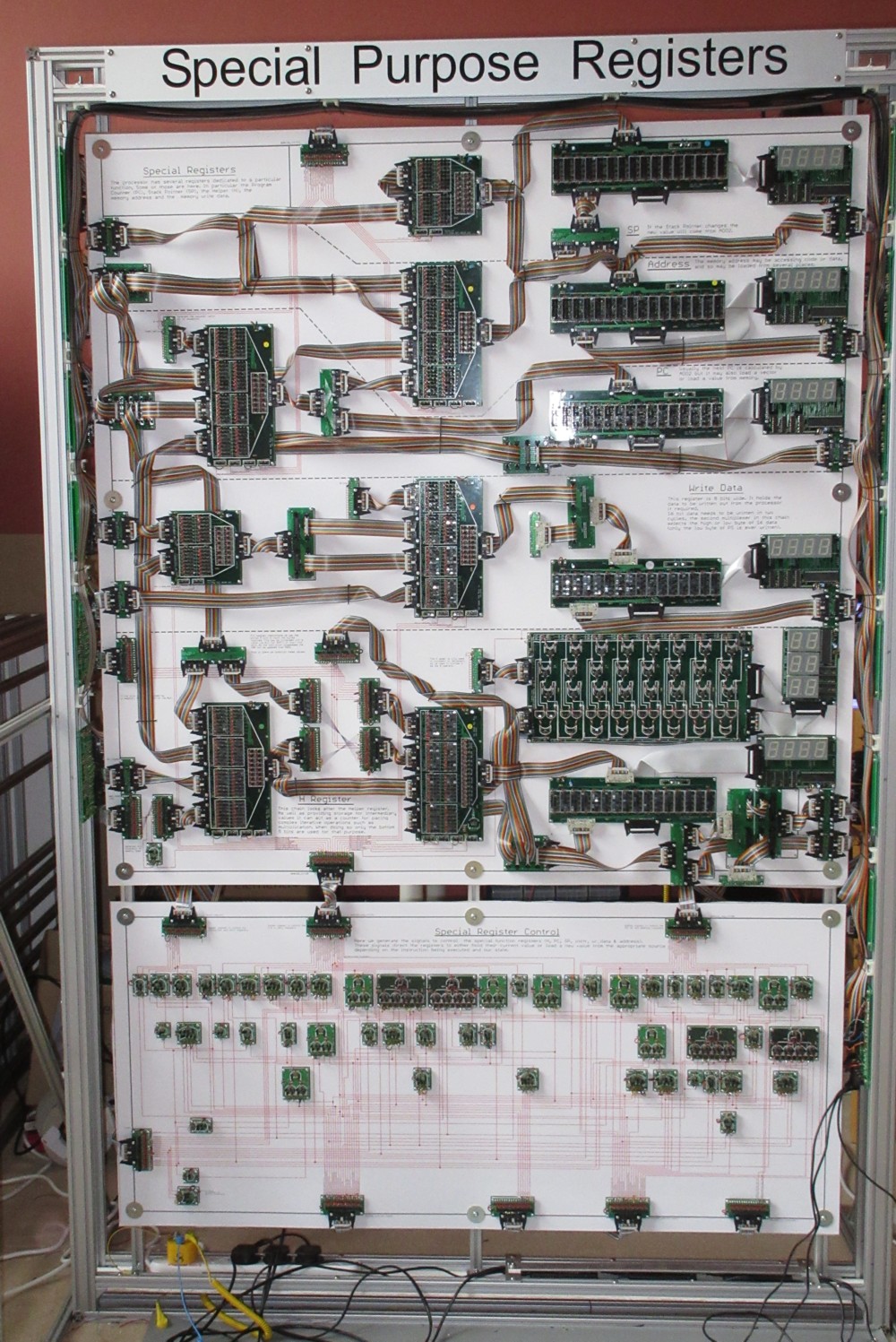
Arithmetic & Logic Unit (ALU)
This is where all the sums are carried out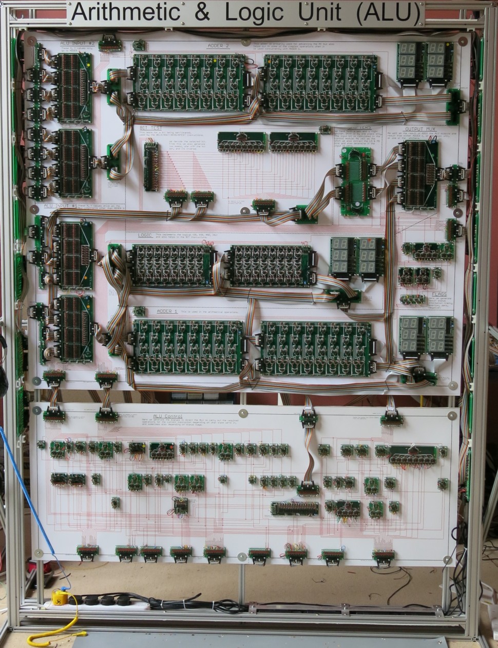
General Purpose Registers
The R0..R3 registers live in the top left module. The top right module multiplexes the registers to generate the RA and RB data buses which are the usual arguments for arithmetic operations. The lower module generates the control signals.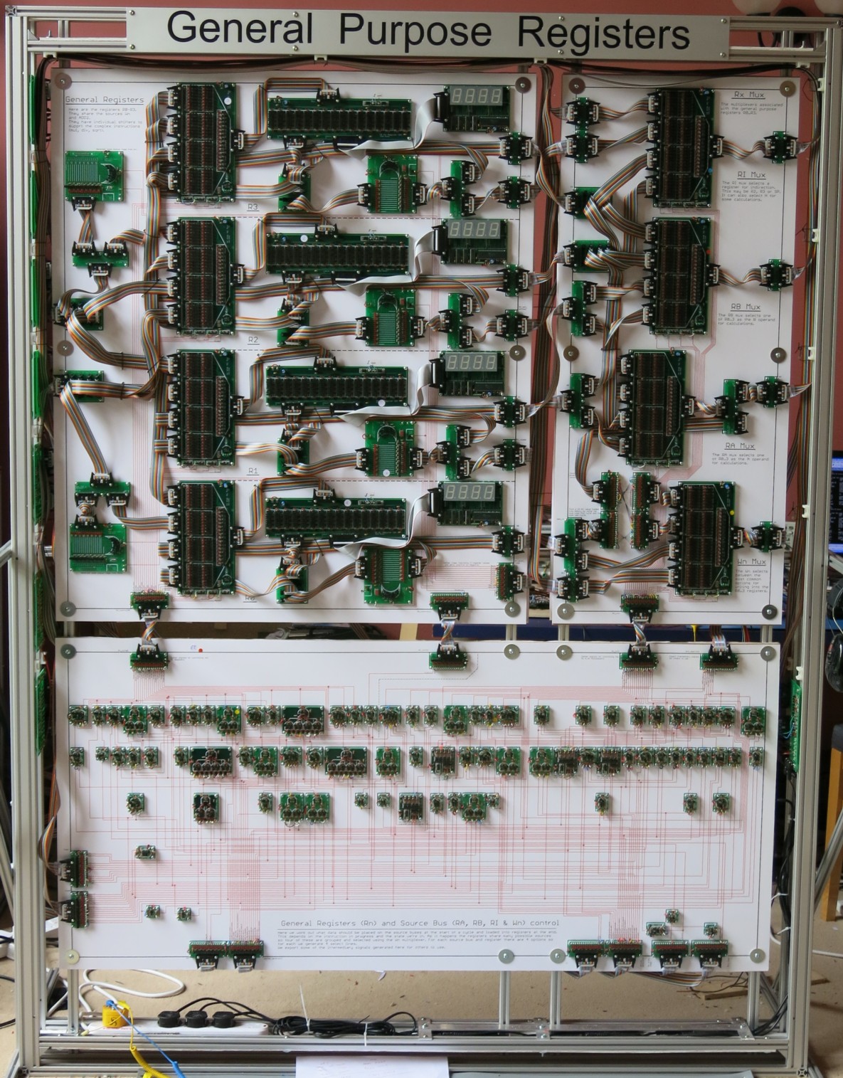
Control & I/O
This is where the Megaprocessor meets the outside world. The interface section makes up the top half. On the lower right is the control board which generates clock and reset. To teh left are the peripherals. A PC is mounted in the frame to act as a host (program download).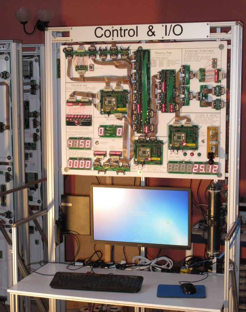
Memory
This provides 256 Bytes of RAM. And LED on each bit; which means it can also act as a dot matrix display of 32 × 64 LEDs.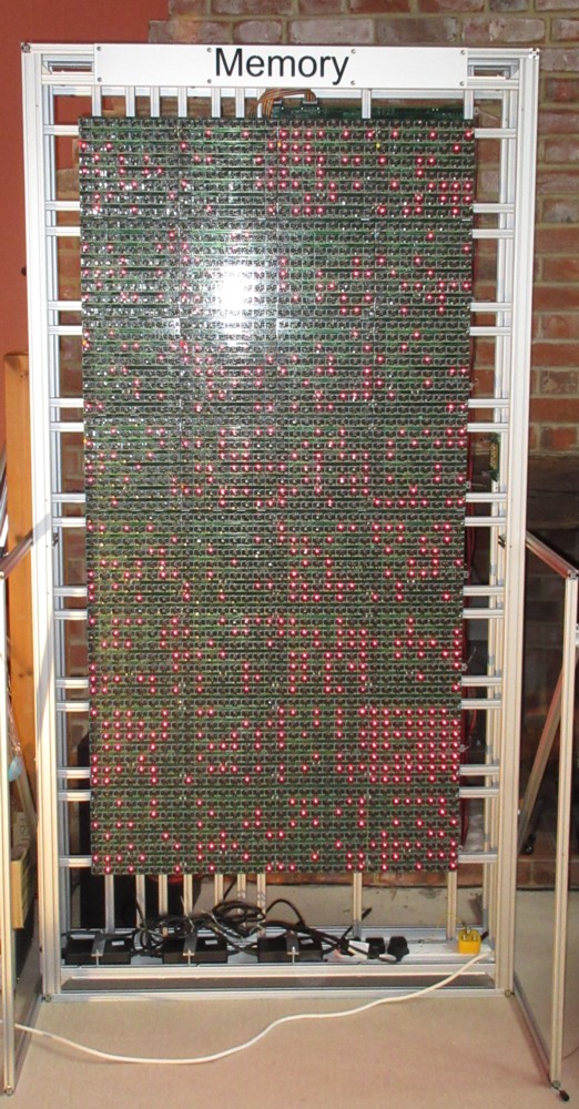

© 2014-2016 James Newman.