 Speed 2
On the previous page I described how my error with pullup resistors led to the speed of the megaprocesor being somewhat lower than I'd hoped. This was a bit sad but I didn't start to fully pay for my crimes against electronics until it came to integration.
At the end of a processor cycle the registers are updated. Registers are made up of master slave latches so this is done by sending two short pulses of 2μs each from the control frame down the processor from frame to frame. Its a long way from one end to the other and there's a fair number of connections on the way so I regenerate the pulses on each frame. Now when I discovered the pullup problem whilst measuring the adder I realised that I would have to also change the pull ups on the services board which is where I do the regeneration.
I forgot to do it.
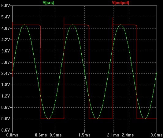
For the first stage of integration I used an FPGA to emulate most of the processor whilst I tested the control. It mostly worked but was a little erratic. Looking at the pulses I saw this:
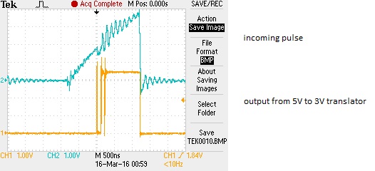
No wonder the poor FPGA got confused. Now it is possible to argue (I won't) that the ugly nature of the pulse doesn't matter to the real megaprocessor as it's being used to control a latch and just one of a master slave combination. So this horrible signal would cause the master to load its data. And then later on a similarly ugly pulse but on a completely different wire would cause the slave to load its data from the master and everything would be fine (the FPGA is/was edge triggered so is more vulnerable). But its horrible and the megaprocessor deserves better. The other thing to notice is that the incoming pulse is not only sawtooth rather than rectangular, but it is only 1μs long. Where's my other microsecond ? This is important; if you start with a two microsecond pulse but lose a microsecond at each regeneration then going through five regenerations to get to the far end of the processor is not going to end well.
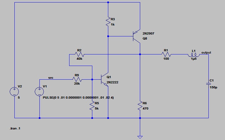
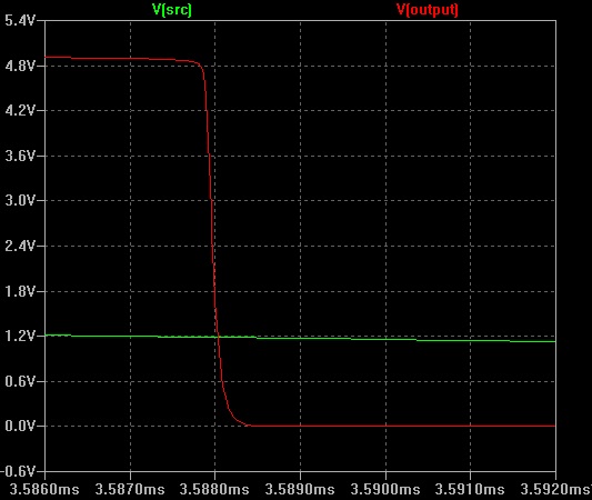
Rather than just swap the pullup resistor and see what happened I thought I should try and understand a bit better what was happening and try simulating the circuit and see if the behaviour could be explained or if I should go hunting for some additional problem. The circuit I used was:
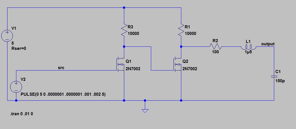
The few passives on the right are my attempt to model the cable. 100Ω impedance, 500μH/m and 50pF per meter. Three meters long. They made little difference in the simulation. The simulation showed a rise time of maybe 1.5μs
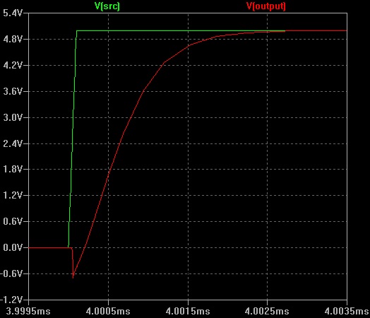
and a fall time of maybe 0.5μs.
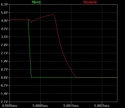
So to a first approximation it matches my experimental observation of a resulting sawtooth and a missing micro-second.
Changing the pullup resistors to 1k improved things as you might expect.
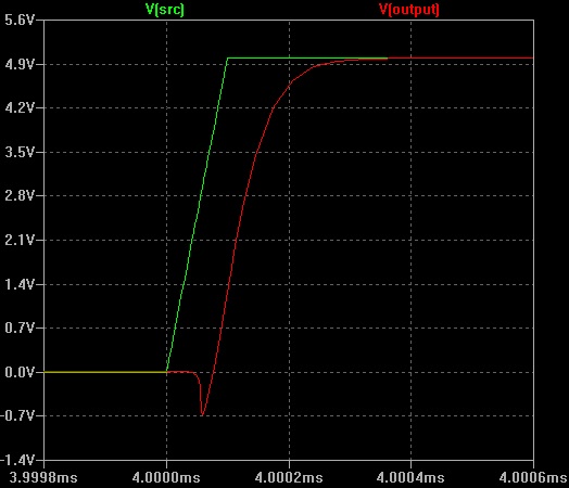
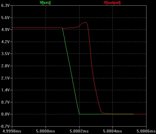
with rise and fall times both about 100ns.
I could have settled for that but I had noticed the jagged nature of the scope trace and thought I should at least think about upgrading to a Schmitt trigger. This is much more advanced stuff and I struggled a bit. I came across this website, plagarised one of the circuits and played with LTSpice to come up with this:
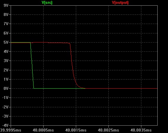
I tested it with a sine wave input and got a rather nice square wave out with plenty of hysteresis.
And the rise/fall times were pretty good as well, 100ns or so.
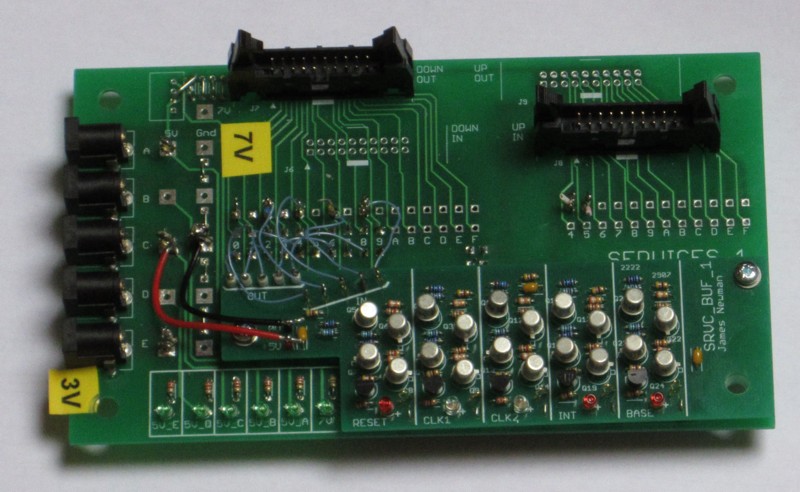
This looked very promising so I decided to implement it and made up a little piggyback board to upgrade the sevices board
The regeneration looked good ! Output was nice and square and was no longer abbreviated. So I was happy. Briefly. Checking again I noticed that the pulse was now too long, by about a microsecond.
I'd messed up again. In the simulation I'd only checked the behaviour with a sine wave assuming that if it behaved sensibly with that then it would be fine in my application. Which is kind of (but not really) fair enough. I was hunting for microseconds, I should have looked more closely. Running LTSpice with a square wave input we find that whilst the rise and fall edges are fast, they're also delayed. By about a 0.25 and 1.5 microseconds respectively.
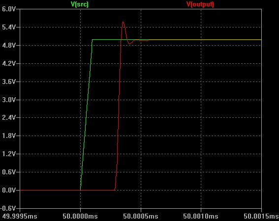
Gaining a microsecond is not as bad as losing one, but it's not great either. I did start looking into what was happening but realised that this was going to take a bit of time and I wanted to get on with integration. So I threw in the towel and stuck with my simple buffer but with the smaller pullup resistors.
An expensive lesson.
- Home
- Vital Statistics
- Progress
- Architecture
- Stepping Stones
- Programming
- Peripherals
- Construction
- Cost & Materials
- Good, Bad & Ugly
- History
- Build Faults
- Flip Flops
- Modelling
- Architecture Choice
- Logic Type
- 7 segment
- Board Shape
- Dual Output
- ALU
- SRAM
- Speed
- Speed 2
- Buses
- Area
- Efficiency
- LED supply
- Multiplexor Problem
- Multiplexor Errors
- Surface Mount
- Solder
- Health & Safety
- Web
- Links
- Contact

© 2014-2016 James Newman.